
Please Leave Us A Message
Privacy statement: Your privacy is very important to Us. Our company promises not to disclose your personal information to any external company with out your explicit permission.


Packaging: Carton box
Productivity: 1000000000 pcs/week
Transportation: Ocean,Land,Air
Place of Origin: China
Supply Ability: 7000000000 pcs/week
Certificate: GB/T19001-2008/ISO9001:2008
HS Code: 8541401000
Port: SHENZHEN
Payment Type: T/T,Paypal,Western Union
Incoterm: FOB,EXW,FCA
Model No.: 312URD-3.5HK
Brand: Best LED
LED Type: Through-Hole Led
Lens Type: Red Diffused Lens
Wavelength: 630nm
Chip Quantity: 1 Chip
Color: Red
Main Application: Led Indicator
Install: Board Mount Led
Level: Single Level Indicator
Angle Of LED Pins: Right Angle
| Selling Units: | Piece/Pieces |
|---|---|
| Package Type: | Carton box |
| Download: |
|

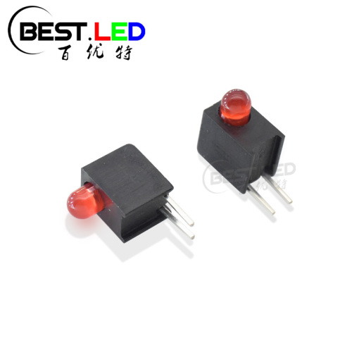
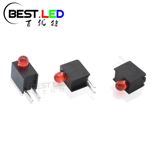
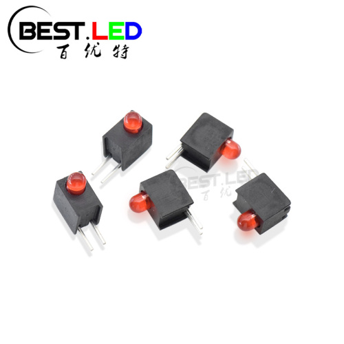
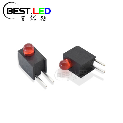
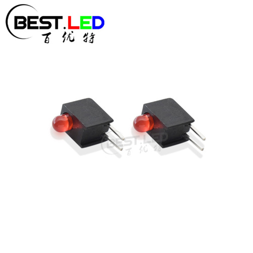
3mm red diffused led Single Level Circuit Board Indicator
This circuit board indicator are acutally made by 3mm Red Through-Hole LED inside and cover with a black case that can bent the LED pins as right angle. We finished the red LED Lamps at first, and then we need to install this red LED(625nm LED) into the black plastic case. In this circuit board indicator, we produce this Red Through-Hole LED inside as a red diffused lens, which can make this emitting light be more soft and easy to see directly. But if you don't want this red diffused lens, it's also available in clear lens, milky lens ect. On the other hand, this LED are also available in different colors, which is widely use in diagnostic, industrial equipement and data storage application. Less PC board space needed, height and spacing alignment saves assemnly cost. If you are interested in this 312URD-3.5HK right angle LED circuit board indicator, just feel free to contact us for more information~

Size of LED circuit board indicator:

Notes:
1, All dimensons are in millimeters;
2, Tolerance is ±0.10mm unless otherwise ntoed;
3,590nm LED(Yellow), 520nm LED (Green) or 470nm LED (Blue) are also available in this case.
Absolute Maximum Ratings(Tc=25℃)
| Parameter | Symbol | Rating | Unit |
| Power Dissipation | Pd | 105 | mw |
| Pulse Forward Current | IFP | 100 | mA |
| Forward Current | IF | ≤30 | mA |
| Reverse Voltage | VR | 5 | V |
| Junction Temperature | Tj | 100 | ℃ |
| Operating Temperature | Topr | -40 - +80 | ℃ |
| Storage Temperature | Tstg | -40 - +100 | ℃ |
| Soldering Temperature | Tsol | 260 | ℃ |
| Electro-Stati-Discharge(HBM) | ESD | 2000 | V |
| Service lige under normal conditions | Time | 80000 | H |
| Warranty | Time | 2 | Years |
| Antistatic bag | Piece | 1000 | Back |
*Pulse forward current confition: Duty 1% and Pulse width=10us.
*Soldering confition: Soldering confition must be completed with 3 secongds at 260℃
| Parameter | Symbol | Min | Typ | Max | Unit | Test Condition |
| Forward voltage | VF | 1.8 | 1.9 | 2.4 | V | IF=20mA |
| Luminous Intensity | IV | 300 | | 500 | mcd | IF=20mA |
| Peak Wavelength | λP | | 633 | | nm | IF=20mA |
| Dominant Wavelength | λd | 620 | 625 | 630 | nm | IF=20mA |
| Half Width | △λ | | 12 | | nm | IF=20mA |
| Viewing Half Angle | 2θ1/2 | | ±22 | | deg | IF=20mA |
| Revers Current | IR | | | 5 | uA | VR=5V |
*θ1/2 is the off-axis angle at which the luminous intensity is half the axial luminous intensity;
Main application:
*Diagnostic or panel status indicator;
*Industrial equipment;
*Data storage equipment;

Detail:
This Red Through-hole LED are made with Gap material chip, which have high reliability, high radiant intensity;
With pure gole wilre, famous branded, high quality epoxy and high quality LED frame. This LED circuit board indicator will wor perfectly for your project!

Precautions:
1, A moisture barrier bag(MBB)containing LEDS shall be kept in an environment with temperature below40C and humidity below 90% RH. A MBB shall be kept sealed until the LEDS contained in that bag are to be used immediately.Storge in an environment with temperature 5-30 C and humidity below 60% RH
2. After a MBB has been opened, all LEDS contained in that bag shall complete soldering process withinaccording to the conditions listed on the Best LED MBB.
3. If the 10% spot of a humidity indicator card (HIC)indicates wet, LEDS shall be baked according tothe conditions listed on the Best LED MBB.
4. During soldering, component covers and holders should leave clearance to avoid placing damagingstress on the LED during soldering.

5 . The tip of the soldering iron should never touch the lens epoxy;
6 . After soldering , allow at least three minutes for the component to cool down to room temperature before further operations;
7 . If the LED will undergo multiple soldering passes or face other processes where the part may be subjected to intense heat , please check with Best LED for compatibility;
8 . Recommended Reflow Soldering Profiles For SMD Housing LEDS;

Notes:
1, We recommend the reflow temperature 245℃(±5℃). The maximum soldering temperature should be limited to 260℃.
2, Don't cause stress to the epoxy resin whilte it is expossed to high tempreature.
3, Recommended solder: Sn/Cu/Ag;
4, No more than once;
Tel: 86-0755-89752405
Whatsapp: +8615815584344
Address: No.3, Lida alley, Qiuwu community, Longgang District, Shenzhen, Guangdong, China. 518116, Shenzhen, Guangdong China
Website: https://www.bestsmd.com


Privacy statement: Your privacy is very important to Us. Our company promises not to disclose your personal information to any external company with out your explicit permission.
Fill in more information so that we can get in touch with you faster
Privacy statement: Your privacy is very important to Us. Our company promises not to disclose your personal information to any external company with out your explicit permission.