Privacy statement: Your privacy is very important to Us. Our company promises not to disclose your personal information to any external company with out your explicit permission.


Packaging: Carton box
Productivity: 1000000000 pcs/week
Transportation: Ocean,Land,Air
Place of Origin: China
Supply Ability: 7000000000 pcs/week
Certificate: GB/T19001-2008/ISO9001:2008
HS Code: 8541401000
Port: SHENZHEN
Payment Type: T/T,Paypal
Incoterm: FOB,EXW,FCA
Model No.: 513ERC62D3L12
Brand: Best LED
Supply Type: Original Manufacturer
Reference Materials: Datasheet
Place Of Origin: China
Species: Led
Package Type: Through Hole
LED Type: Through-hole LED
Chip Quantity 5mm IR LED: 1 Chip
Main Application: Medical Applications; IR System
Viewing Angle: 20 degree
Color: Deep Red LED
Lens Type: Clear Lens Without Edges
Wavelength: 620nm

5mm Light Emitting Diode electronics components;
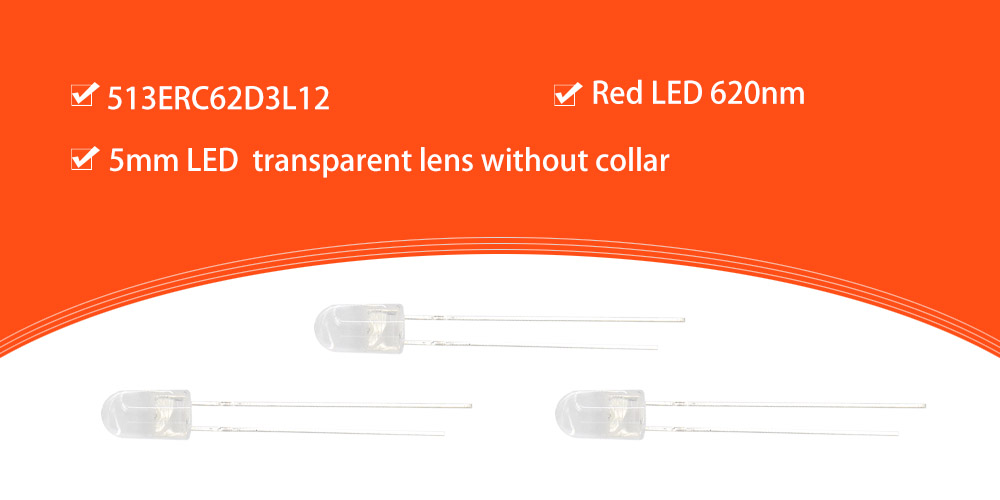
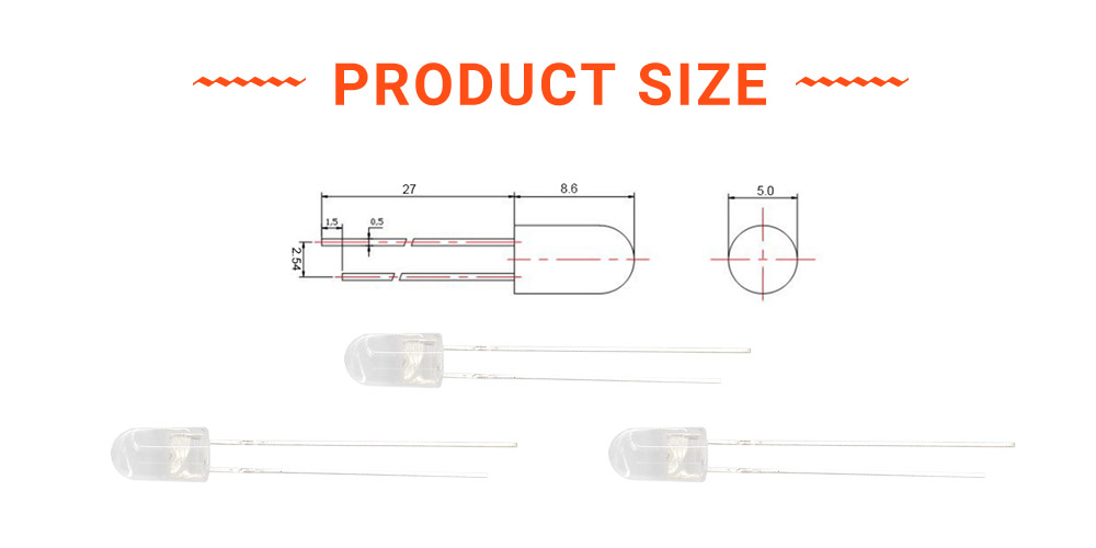
This is a Super Bright Red Through-Hole LED with transparent lens as follow. Similar with most of 5mm Red LED, it also got the 5mm diameter. The only different between 513ERC62D3L12 and 503ERC62D3L12 is the edges(or the collar) at the bottom of LED Lamps lens. In this 513ERC62D3L12, there are the totally cylindrical epoxy lens from the top to bottom. Which have no any edges on the epoxy lens, that will make LED fit into the PCB or case totally without any block.

SMD LED Features:
Dimension: 5mm;
Wavelength: 980nm LED;
Lens type: Clear epoxy;
High reliability and high radiation intersity;

Electrical Parameters:
| Parameter | Symbol | Rating | Unit |
| Power Dissipation | Pd | 200 | mw |
| Pulse Forward Current | IFP | 500 | mA |
| Forward current | IF | ≤150 | mA |
| Reverse Voltage | VR | 5 | V |
| Junction Temperature | Tj | 115 | ℃ |
| Operating Temperature | Topr | -40 - +80 | ℃ |
| Storage Temperature | Tstg | -40 - +100 | ℃ |
| Soldering Temperature | Tsol | 260 | ℃ |
| Electro-Stati-Discharge(HBM) | ESD | 2000 | V |
| Service lige under normal conditions | Time | 60000 | H |
| Warranty | Time | 2 | Years |
| Antistatic bag | Piece | 1000 | Back |
*Pulse forward current confition: Duty 1% and Pulse width=10us.
*Soldering confition: Soldering confition must be completed with 3 secongds at 260℃
| Parameter | Symbol | Min | Type | Max | Unit | Test Condition |
| Forward Voltage | VF | 1.0 1.1 1.2 | 1.2 1.4 | 1.3 1.4 1.6 ≤2.0 | V | IF=20mA IF=50mA IF=100mA IF=150mA |
| Radiant Intensity | IE | 80 240 | 550 | 120 300 | mW/sr | IF=20mA IF=50mA IF=100mA |
| Luminous Power | PO | | 30 200 | | mw |
IF=50mA IF=100mA |
| Peak Wavelength | λP | 970 980 990 |
| IF=50mA | ||
| Half Width | λ△ |
| 50 |
| nm | IF=50mA |
| Viewing Half Angle | 2θ1/2 | | ±10 |
| deg | IF=50mA |
| Reverse Current | IR | | | 5 | uA | VR=5 |
*Luminous intensity is measured by ZWL600.
*λD is derived from the CIE chromaticity diagram and represents the single wavelength which defines the color of the device.
Storage Conditions:
1. avoid continued exposure to the condensing moisture environment and keep the product away from rapid transitions in ambient temperature;
2. LEDs should be stored with temperature ≤30℃ and relative humidity<60%℃;
3. Product in the original sealed package is recommended to be assembled within 72 hours of opening;
4. Product in opened package for more than a week should be baked for 6-8 hours at 85-10℃;
LED MOUNTING METHOD
1, The lead pitch of the LED must match the pitch of the mounting holes on the PCB during component placement;
Lead-forming may be required to insure the lead pitch matches the hole pitch;
Refer to the figure below for proper lead forming procedures;
Do not route PCB trace in the contact area between the leadframe and the PCB to prevent short-circuits;

Noted:
○ Correct mounting method;
× Incorrect mounting method;
2. When soldering wires to the LED, each wire joint should be separately insulated with heat-shrink tube to prevent short-circuit contact.
Do not bundle both wires in one heat shrink tube to avoid pinching the LED leads;
Pinching stress on the led leads may damage the internal structures and cause failure;

Noted:
○ Correct mounting method;
× Incorrect mounting method;
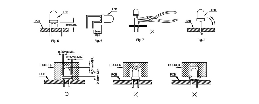
3. Use stand-offs(Fig 3)or spacers(Fig 4)to securely position the LED above the PCB;
4. Maintain a minimum of 3mm clearance between the base of the LED lens and the first lead bend (Fig. 5. Fig. 6)
5. During lead forming, use tools or jigs to hold the leads securely so that the bending force will not be transmitted to the LED lens and its internal structures;
Do not perform lead forming once the component has been mounted onto the PCB;

Lead Forming Procedures
1. Lead Forming Procedures;
2. Do not bend the leads more than twice (Fig. 7);
3. During soldering, component covers and holders should leave clearance to avoid placing damaging stress on the LED during soldering(Fig 8);
4. The tip of the soldering iron should never touch the lens epoxy;
5. Through-hole LEDs are incompatible with reflow soldering;
6. If the LED will undergo multiple soldering passes or face other processes where the part may be subjected to intense heat please check with Best LED for compatibility;

Tel: 86-0755-89752405
Whatsapp: +8615815584344
Address: No.3, Lida alley, Qiuwu community, Longgang District, Shenzhen, Guangdong, China. 518116, Shenzhen, Guangdong China
Website: https://www.bestsmd.com


Privacy statement: Your privacy is very important to Us. Our company promises not to disclose your personal information to any external company with out your explicit permission.

Fill in more information so that we can get in touch with you faster
Privacy statement: Your privacy is very important to Us. Our company promises not to disclose your personal information to any external company with out your explicit permission.